
搜索到
25
篇与
的结果
-
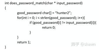
 RISC-V CPU侧信道攻击原理与实践 https://zhuanlan.zhihu.com/p/393106129RISC-V作为一种全新的开源CPU指令集体系结构(ISA),目前无论是在高校与各研究机构,还是商业应用中,皆方兴未衰,大有与X86和ARM形成成三足鼎立之势。但对于RISC-V CPU本身的安全, 却资料少而凌乱,晦涩难懂,面目狰狞,拒人于千里之外。故有此冲动,写几篇有关RISC-V CPU侧信道攻击的文章,介绍RISC-V CPU侧信道攻击的原理和作者本人的实践;作者研究CPU侧信道攻击的初衷也是为“防守”,意在为某款RISC-V CPU提供一个安全性验证平台,验证该CPU安全设计加固方案之有效性。我将用一系列文章来来介绍:什么是CPU侧信道攻击?导致CPU产生侧信道攻击风险的微架构设计技术Spectre攻击的种类与攻击方法细节;Meltdown攻击原理与工具过程;降低CPU侧信道攻击风险的手段那就让我们开始吧。侧信道攻击概述1.1什么是侧信道攻击1.1.1 日常生活中的侧信道攻击在科技日新月异的今天,在享受高科技带来的幸福感的同时,我们的隐私也会在不知不觉中从各种渠道被泄露出去,有些甚至你完全想不到,可以说防不胜防,比如说,你想过单从按键声音就分析出你的手机号码么?大家可能听说过网友“清华南都”就根据一段视频中的按键音,还原出了360总裁周鸿祎的手机号。事情起源于优酷的记者电话采访周鸿祎先生的一段视频. 在视频的第33-43秒,记者与周鸿祎先生进行了电话连线,视频播放把整个拨号过程也原封不动地播放了出来,包括在电话拨号阶段的产生的电话拨号音,“清华南都”就根据这段拨号音结合一些DTMF(双音多频, Dual-tone multi-frequency)的技术基础,破解这个电话号码;在这个事情中,如果把周鸿祎先生的电话号码当做一个高度机密信息(private data)的话,“清华南都”本人并没有看到过周先生的电话号码,也没有采用暴力破解的方式一个个电话号码去尝试,而“清华南都”通过分析声音特征信息获取了该机密信息,这个过程从技术范畴的角度讲就是一种利用了声波信息的“侧信道攻击”。那到底什么是侧信道攻击?维基百科是这么定义的:“在密码学中,侧信道攻击(Side-channel attack)是一种攻击方式,它基于从密码系统的物理实现中获取的信息,而非暴力破解法或是算法中的理论性缺陷,例如利用时间信息、功率消耗、电磁泄露或甚是声音可以提供额外的信息,来对系统的破解。”这个定义对于非密码学行业从业人员来讲还是非常抽象的。我们简单一点理解就是利用一些“旁门左道”的手法来获取我们需要的机密信息;比如我们经常在电视剧中看到的一个场景:一个窃贼将听诊器压在保险柜的前面板上,通过内部的机械声来打开保险柜。小偷会慢慢地转动转盘,听着内部机械结构所泄露出的咔哒声或阻力声,来分析保险箱齿轮的内部运作,并从而得知其密码的组合。除了拨号盘上的数字和保险柜“是”或“否”的打开状态以外,这个保险柜并不会给用户任何反馈。但保险箱的物理机械所产生的那些微小的触动和声音线索,这也是一个典型的侧信道攻击。某网站(https://www.wired.com/story/lamphone-light-bulb-vibration-spying/...)曾经公布了一项新技术(lamphone):“通过使用望远镜观察室内悬挂的灯泡的振动(通过灯泡所发出的光的微弱变化),可以实时窃听房间内的对话”。这种技术将测信道攻击变得更加具有广泛性。1.1.2 计算机领域的侧信道攻击计算机领域的侧信道攻击是利用计算机不经意间释放出的信息信号(如电磁辐射,电脑硬件运行产生的声音)来进行破译的攻击模式:例如,黑客可以通过计算机显示屏或硬盘驱动器所产生的电磁辐射,来读取你所显示的画面和磁盘内的文件信息;或是,通过计算机组件在执行某些程序时需要消耗不同的电量,来监控你的电脑;亦或是,仅通过键盘的敲击声就能知道你的账号和密码。最早的计算机侧信道攻击之一,是美国国家安全局(National Security Agency)所称的TEMPEST。1943年贝尔实验室发现,每当有人在电传打字机上打字时,电传打字机会导致附近示波器的读数移动。贝尔实验室的研究人员很快意识到这一问题。电传打字机的目的是为了实现安全、加密的通信,但任何接近它的人,只要能读到它的电磁辐射,就有可能破译它的秘密。这种现象直到1985年才被完全公开记录下来,当时一位名叫维姆·范·埃克(Wim van Eck)的计算机研究人员发表了一篇论文,这就是后来被称为 "屏幕辐射窃密(van Eck phreaking)",即通过远距离检测电脑屏幕放电的电信号,在电脑屏幕上重建图像。计算机领域的侧信道攻击,目前使用最为广泛的攻击手段就是基于时序的攻击(timing attack)。讲了那么多故事,让我们来看一段代码直观地了解一下什么是时序攻击:这是某产品中的一个秘钥比对函数,假设这个函数的用户无法看到源码(也不进行反汇编),我们只是通过库函数的头文件知道这个函数接口定义为int does_password_match(char * input_password)。那我们怎么能够快速地获取函数内部设定的机密信息strPrivateKey的值呢?你可能首先想到的是采用暴力破解方式,逐一尝试各种字符组合,直到函数返回true为止;如果这个秘钥只使用字母和数字,并且秘钥的最大长度7,那你需要尝试的最大次数为62**7=3,521,614,606,208【注26大写字母+26小写字母+10数字)。如果我们利用一下这个函数的timing信息,测量一下这个函数的处理时间,我们其实可以有一种更为快捷的方法,我们可以采用逐位破解的方法快速地完成这个任务;因为我们输入的密码与机密信息的匹配度越高,该函数的处理时间越长,这样我们通过测量这个函数的处理时间就可以判断前面的第一位,第二位,第三位等是否验证通过;则最坏的尝试的次数为62*7=434;用这种方式实现的一个产品(比如密码门禁系统),通过采用timing-attack的方法,其破解是完全可以通过人力的方式在数分钟内完成的;1.1.3 CPU的侧信道攻击目前随着超标量CPU技术的飞速发展,其处理性能大幅提升的同时, 以计算机为中心的侧信道攻击也变得更加复杂和手段多样。所谓道高一尺,魔高一丈; 2018伊始,两个芯片级漏洞Meltdown(熔断)、Spectre(幽灵)漏洞震惊了安全界。受影响的CPU包括Intel、AMD和ARM,基本囊括的消费级CPU市场的绝大部分。Meltdown漏洞可以在用户态越权读取内核态的内存数据,Spectre漏洞可以通过浏览器的Javascript,读取用户态的内存数据。这两个漏洞摧毁了公有云的基石(用户数据隔离),因为通过Meltdown和Spectre的攻击,用户在虚拟机里就可以无限制的读取宿主机或者其他虚拟机的数据。Spectre、Meltdown等攻击方式利用了微处理器的 "微架构"设计中的这些特性(站在安全的角度也可以叫漏洞,包括但不局限于分支预测,推断执行,乱序执行,等)。随着计算机变得越来越复杂,如果计算行业继续优先考虑性能而不是安全,侧信道攻击将会越来越猖獗,今天一个你看似巧妙的设计,非常有可能成为明天攻击的一个突破口。1.2 侧信道攻击的分类对于CPU侧信道攻击,很多公司(比如google和微软)成立了专门的安全团队,用来发现目前市场上主流CPU的安全风险并提供安全解决方案以降低危害(mitigation of the risk)。 随着对上述meltdown和Spectre攻击方式的研究深入,越来越多的基于meltdown和spectre的变种被开发了出来。参考文献[A Systematic Evaluation of Transient Execution Attacks and Defenses]对瞬态执行攻击进行了系统的分析,并把当前已经发现的针对CPU微架构的侧信道攻击方法进行了总结与归类(见图),文献的作者认为当前大部分的安全防护方法无法有效应对当前如此多的攻击方式带来的安全风险。本系列文章主要描述如下几种Spectre变种攻击方式:• Variant 1 (Spectre_PHT): bounds check bypass• Variant 2 (Spectre_BTB): branch target injection• Variant 4 (Spectre_STL): Store bypass• Variant 5 (Spectre_RSB): Return Stack Buffer【注:PHT: Pattern History Table, BTB:Branch Target Buffer, STL:Store To Load, RSB:Return Stack Buffer】Meltdown属于 Variant 3, Meltdown还可以进一步细分为:• Meltdown-US(Supervisor-only Bypass)• Meltdown-P(Virtual Translation Bypass)• Meltdown-GP(System Register Bypass)• Meltdown-NM(FPU Register Bypass)• Meltdown-RW(Readonly Bypass)• Meltdown-PK(Protection Key Bypass)• Meltdown-BR(Bounds Check Bypass)我们重点关注高性能CPU的一些通用设计带来的风险,而对于某些厂家独特设计带来的问题,本文不做过多的描述。
 -
在verilog或者systemverilog中通过systemverilog获得环境变量setenv,getenv 在芯片验证的仿真中,有时候需要从文件中加载一些数据,比如激励、初始化数据、code等等,这些文件路径可以用绝对路径,当然为了其他人也可以用,最好用相对路径,这就需要用到环境变量来做路径的前半段。在module中得到或设置系统环境变量需要用到systemverilog的DPI-C,import C函数,然后在module中的块语句中调用C函数。步骤如下:在要获得环境变量的文件中 import setenv和getenv如下所示,把这两个函数import进去,不需要定义对应的C函数import "DPI-C" function int setenv(input string env_name, input string env_value, input int overwrite);import "DPI-C" function string getenv (input string env_name);直接使用getenv, setenv来获得和设置环境变量module mem read( input [8*200-1: O] mem_file ); initial begin $display("mem_file is %Os", mem_file); end endmodule module dut ( input clk, input wire [31:0]addr, output [31:0] rdata, input [31:0] wdata, input wire wr ); string path; initial begin setenv("PRJDIR", "/project/uart", 1); path = getenv( "PRJDIR"); $display("PRJDIR is %Os", path); setenv( "PRJDIR", "/project/sp", 1); path = getenv( "PRJDIR"); $display("PRJDIR is %0s", path); end mem_read u_mem_rd(.mem_file(path)); endmodule————————————————版权声明:本文为CSDN博主「甲六乙」的原创文章,遵循CC 4.0 BY-SA版权协议,转载请附上原文出处链接及本声明。原文链接:https://blog.csdn.net/m0_38037810/article/details/126136552
-
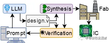
我用ChatGPT设计了一颗芯片 原创 Hammond半导体行业观察2023年12月26日09:53安徽今年早些时候,我(指代本文作者)正在纽约大学从事博士后工作,其中之一是探索Verilog 大型语言模型的使用。我们对使用 ChatGPT 等 LLM 来设计硬件的各种不同应用程序进行了基准测试,包括规范解释、设计以及错误检测和修复。我们是这个领域的先行者之一,早在 2020 年就开始使用 GPT-2 和 Verilog。我立即对上述帖子产生了兴趣,但由于实际流片的成本过高,我们一直使用 FPGA 和模拟。但是,模拟与现实之间总是存在差距,因此表明LLM和人工智能确实可以生产芯片可能对我们的研究领域来说是一个福音。我们能否使用免费流片的Tiny Tapeout 作为实现此目的的工具,并使用LLM不仅编写 Verilog,还为真正的芯片设计 Verilog?我与我的导师和其他几位博士生进行了交谈,我们集思广益了一些想法。Tiny Tapeout 非常小,只有 1000 个标准单元左右,这意味着设计会受到很大限制,但我们都非常喜欢这个想法,特别是因为似乎还没有人做到过,所以如果我们行动迅速,我们可能会能够做到世界第一!所以,我们决定去做。但现在,还有很多其他事情需要考虑。鉴于设计空间如此之小,我们应该提交什么?还有其他问题。我们从我们自己之前的工作中知道,LLM可以编写像 Verilog 这样的硬件设计语言,但他们只是不太擅长,与 Python 等更流行的语言相比,语法或逻辑错误的发生率要高得多,这就是为什么我我的团队已经为 Verilog 制作了自己的LLM的原因。因此,我们需要决定,如果我们确实想使用LLM来制造芯片,(1)我们应该使用哪个LLM?(2)我们应该给它多大的帮助?(3)我们应该尝试什么prompting strategy?设计方法我们首先决定了LLM。我们不会使用到目前为止我们一直在使用的“自动完成”风格的LLM,主要是 OpenAI 的 Codex 和 Salesforce CodeGen,而是使用更新、更华丽的“对话”/“指导”风格的法学硕士。我们选择了 OpenAI 的 ChatGPT 3.5 和ChatGPT 4 版、Google 的 Bard 以及开源的 HuggingChat。然后我们想出了两种方法。第一种方法是尝试让LLM在一种反馈循环中完成所有事情,从而为LLM提供一个规范,然后为该设计生成设计和测试。然后,人类将在模拟器 (iVerilog) 中运行测试和设计,然后将任何错误返回给LLM。然而,我们从经验中知道,LLM有时也相当愚蠢,并且可能会陷入循环,他们认为自己正在解决问题或改进输出,而实际上他们只是迭代相同的数据。因此我们推测有时我们可能需要回馈“人类援助”。通过一些初步实验,我们决定了一个如下所示的初始流程:理想情况下,人类不需要提供太多输入,但这还有待观察。在硬件流片方面,我们的目标是 Tiny Tapeout 3,它将基于 Skywater 130nm。它有一些限制:前面提到的 1000 个标准单元,以及只有 8 位输入(包括任何时钟或复位)和 8 位输出。Tiny Tapeout 使用 OpenLane,这意味着我们也仅限于可综合的 Verilog-2001。设计什么?在这个实验的早期阶段,我们对与对话式LLM交互的标准化和(理想情况下)自动化流程的潜力感兴趣,该流程将从规范开始并产生该设计的硬件描述语言。鉴于我们有 8 位输入,我们决定使用其中 3 位来控制设计选择多路复用器,以适应 8 个小型基准测试。如果这些进展顺利,我们就会致力于更雄心勃勃的事情。这些是我们提出的基准:每个基准测试都有一个简短的规范来描述它及其 I/O,以及正确的预期行为。然后,纽约大学博士后Jason Blocklove 与四个选定的LLM(ChatGPT-3.5、ChatGPT-4、Bard 和 HuggingChat)坐在一起,执行前面描述的过程,引导LLM首先生成设计,然后生成测试平台,然后将它们一起模拟,并反馈任何错误。有时,谈话中需要考虑特殊情况。由于模型在一次响应中可以给出的输出量受到限制,文件或解释通常会被中断;在这些情况下,模型将提示“请继续”。continue 之后的代码通常从较早消息的最后一行之前开始,因此当代码被复制到文件中进行编译和模拟时,它会被编辑以形成一个内聚块。然而,这个过程没有添加额外的 HDL。同样,有时响应中会包含让用户添加自己的代码的注释。如果这些注释会阻止功能,例如留下不完整的值数组,则将重新生成响应,否则将保持原样。设计提示:我们在这个环节设计的提示词看起来像这样:在试过之后,我们发现返回的设计质量参差不齐,我们发现只有 ChatGPT-4 可以可靠地生成设计。以下是每个LLM的第一个设计(移位寄存器)的示例:1、首先我们看一下ChatGPT 4.0生成的反馈:这个代码是有用的。2.我们再试一下ChatGPT 3.5,生成的结果如下:同样有用。3.我们再试一下BARD,得出以下结果。这是行不通的!请注意输入定义中的错误。4.再看一下HuggingChat从以上代码看来,它似乎已经疯了。测试平台(Testbenches)一旦我们有了设计,我们就必须提示建立一个测试平台,在这里,我们将用以下提示词:Can you create a Verilog testbench for this design? It should be self-checking and made to work with iverilog for simulation and validation. If test cases should fail, the testbench should provide enough information that the error can be found and resolved.以下是完整的对话事例:1.我们先看一下ChatGPT 4.0生成的回复。我们首先问:得到的回复如下:以下是代码的快速细分:1.Define the shift_register module with the specified inputs and outputs.2.Create an always block that responds to the rising edge of the clock (posedge clk) or the falling edge of the active-low reset (negedge reset_n).3.Within the always block, check if the reset signal is low (!reset_n). If so, clear the 8-bit output register (data_out <= 8'b0).4.If the reset signal is not low, check if the shift enable signal is high. If so, shift the data in the output register to the left and insert the new data bit at the least significant bit position (data_out <= {data_out[6:0], data_in}).该设计满足给定的规格,并提供具有所需输入和输出的 8 位移位寄存器。接下来我又问:Can you create a Verilog testbench for this design? It should be self-checking and made to work with iverilog for simulation and validation. If test cases should fail, the testbench should provide enough information that the error can be found and resolved.然后得出下面的回答:该测试平台涵盖四个测试用例:简单移位(shift):将 1 移入寄存器并检查输出。使用交替位进行移位:移位交替位模式并检查输出。没有shift_enable 的移位:验证移位寄存器在没有shift_enable 信号的情况下不会移位。移位操作期间复位:检查移位操作期间寄存器是否正确复位。如果任何测试用例失败,测试台会提供错误消息。如果所有测试用例都通过。接下来,我们又问了一个问题:When running the simulation it gives the following output. Please provide fixed code.Error: Test case 1 failed. Expected: 10000000, Received: 01111111Error: Test case 2 failed. Expected: 10101010, Received: 01010101Error: Test case 3 failed. Expected: 10101010, Received: 01010101All test cases passed!然后,我们得出以下回应:Apologies for the confusion. It appears that the test cases are failing due to incorrect output expectations. I made a mistake in the test case expectations. Let's correct the test cases and update the testbench code:我根据移位寄存器的正确行为更新了测试用例 1、2 和 3 的预期输出。现在,当您运行模拟时,它应该显示“所有测试用例已通过!” 没有任何错误。而事实上,它也确实通过了,没有任何错误!基本结果总体而言,只有 ChatGPT-3.5 和 ChatGPT-4 可以可靠地生成设计,因此我们最终只分析了这两个模型,并将 Bard 和 HuggingChat 从我们的结果中排除。使用两个 OpenAI 模型,我们完成了全套基准测试 3 次,得到了以下结果:命名法( Nomenclature):如果没有报告错误,则设计通过,无需反馈 (NFN:no feedback necessary)。相反,如果这些操作中的任何一个报告错误,它们就会反馈到模型中,并要求“请提供修复。”,称为工具反馈 (TF:tool feedback)。如果相同的错误或类型的错误出现三次,则用户会给出简单的人工反馈(SHF:simple human feedback),通常是通过说明 Verilog 中的哪种类型的问题会导致此错误(例如声明信号时的语法错误)。如果错误继续存在,则提供中等人类反馈 (MHF:moderate human feedback),并向工具提供稍微更有针对性的信息以识别特定错误。如果错误仍然存在,则提供高级人类反馈 (AHF:advanced human feedback),该反馈依赖于准确指出位置错误是什么以及修复它的方法。一旦设计经过编译和仿真且没有失败的测试用例,就被认为是成功的。然而,如果高级反馈无法修复错误,或者用户需要编写任何 Verilog 来解决错误,则测试将被视为失败。如果对话超过 25 条消息(符合 OpenAI 每 3 小时 ChatGPT-4 消息的速率限制),则测试也被视为失败。由此可见,ChatGPT-4表现良好。大多数基准测试都通过了,其中大多数只需要工具反馈。ChatGPT-4 在测试平台设计中最需要的人工反馈。几种故障模式是一致的,一个常见的错误是在设计或测试平台中添加了 SystemVerilog 特定的语法。例如,它经常尝试typedef为 FSM 模型创建状态,或实例化向量数组,而这两种情况在 Verilog-2001 中均不受支持。总的来说,ChatGPT-4 生成的测试平台并不是特别全面。尽管如此,通过随附测试平台的大多数设计也被认为是合规的。两个不合规的“passes”是Dice Rollers,它不产生伪随机输出。测试集 T1 中的Dice Rollers将在一次roll中输出 2,然后在所有后续roll中仅输出 1,无论选择何种die。同时,Dice Roller T3 会改变值,但仅限于快速重复的一小部分(取决于所选die)之间。为了闭合设计循环,我们从 Tiny Tapeout 3 的 ChatGPT-4 对话中合成了测试集 T1,添加了由 ChatGPT-4 设计但未经测试的包装器模块(wrapper module )。整个设计需要 85 个组合逻辑单元、4 个二极管、44 个触发器、39 个缓冲器和 300 个抽头来实现。ChatGPT-3.5的表现明显比 ChatGPT-4 差,大多数对话都导致基准测试失败,并且大多数通过自己测试平台的对话都是不合规的。ChatGPT-3.5 的故障模式与 ChatGPT-4 相比不太一致,每次对话和基准测试之间都会引入各种各样的问题。与 ChatGPT-4 相比,它需要更频繁地修正设计和测试平台。观察结果只有 ChatGPT-4 能够充分满足编写 Verilog 的目的,尽管它仍然需要人类反馈才能使大多数对话成功并符合给定的规范。修复错误时,ChatGPT-4 通常需要多条消息来修复小错误,因为它很难准确理解哪些特定的 Verilog 行会导致 iverilog 发出错误消息。它所添加的错误也往往会在对话之间经常重复出现。ChatGPT-4 在创建功能测试平台方面也比功能设计付出了更多努力。大多数基准测试几乎不需要对设计本身进行修改,而是需要修复测试平台。对于 FSM 来说尤其如此,因为该模型似乎无法创建一个测试平台来正确检查输出,而无需有关状态转换和相应预期输出的重要反馈。另一方面,ChatGPT-3.5 在测试平台和功能设计方面都遇到了困难。更复杂的东西:QTcore-A1在基准测试期间,我是 ChatGPT-4 的学生,现在我已准备好接受更大的挑战,并着手让它为微控制器创建组件。我想知道非结构化对话是否可以提高模型的性能水平,使用一种共同的创造力来更快地编写设计。在这里我要指出的是,我是一位在小型玩具/学术处理器设计方面经验丰富的工程师,曾在奥克兰大学、纽约大学以及现在我所在的澳大利亚悉尼南威尔士大学教授该领域的学生多年。这就是我想要 ChatGPT-4 构建的。知道我们面临着极端的空间限制,我决定采用基于 8 位累加器的架构。使用冯诺依曼设计(共享程序和数据内存)可以节省额外的空间,然后将共享内存限制为仅 32 字节是我对合适的东西的猜测。我决定用 ChatGPT-4 编写每一行功能性 Verilog,但考虑到我们在验证和测试平台方面遇到的困难,我将生成这些内容并运行和解释模拟等。为什么要进行这种设计而不是 RISC-V 之类的设计?众所周知,ISA 的开源处理器有很多实现,例如 RISC-V 和 MIPS。问题是,这意味着 GPT-4 在训练期间已经看到了这些设计。对于这项工作,我不想简单地探索 ChatGPT-4 发出其训练过的数据的能力。相反,我想看看它在制作更新颖的东西时的表现。因此,我使用 ChatGPT-4 本身提供的奇怪 ISA 来引导模型进行全新的设计,我认为这与开源文献中提供的内容完全不同。开始,我问道:Let us make a brand new microprocessor design together. We're severely constrained on space and I/O. We have to fit in 1000 standard cells of an ASIC, so I think we will need to restrict ourselves to an accumulator based 8-bit architecture with no multi-byte instructions. Given this, how do you think we should begin?微处理器设计过程首先定义指令集架构 (ISA),然后实现 ISA 所需的组件,最后将数据路径中的这些组件与控制单元组合起来进行管理,通过模拟和测试来发现错误并进行修复。构建对话对话线程(Conversation threading:):鉴于 ChatGPT-4 与其他 LLM 一样具有固定大小的上下文窗口,我们假设提示模型的最佳方法是将较大的设计分解为子任务,每个子任务都有自己的“对话线程”界面。这使总长度保持在 16,000 个字符以下。当长度超过此值时,专有的后端方法会执行某种文本缩减,但其实现的细节很少。由于 ChatGPT-4 不在线程之间共享信息,人类工程师会将相关信息从前一个线程复制到新的第一条消息中,从而形成一个“基本规范”,慢慢地定义处理器。基本规范最终包括 ISA、寄存器列表(累加器ACC、程序计数器PC、指令寄存器IR)、存储体、ALU 和控制单元的定义,以及处理器在每个周期中应执行的操作的高级概述。本规范中的大部分信息由 ChatGPT-4 生成,并由人工复制/粘贴和轻微编辑。主题(Topics):每个线程一个主题对于处理器的早期设计阶段效果很好(有一个例外,其中 ALU 是在与多周期处理器时钟周期时序计划相同的线程中设计的)。然而,一旦处理器进入模拟阶段并在其上运行程序,我们就发现了规范和实现中的错误和错误。设计工程师没有开始新的对话线程并重建先前的上下文,而是选择在适当的情况下继续先前的对话线程。我们在下面的流程图中对此进行了说明,其中“Cont. T. ID”列指示他们是否“Continued”前一个线程(如果是,则为哪个线程)。重新启动(Restarts):有时 ChatGPT-4 会输出次优响应。如果是这样,工程师有两个选择:(1) 继续对话并推动它修复响应,或者 (2) 使用界面强制 ChatGPT-4“重新启动”响应,即通过假装先前的结果来重新生成结果答案从未出现。在这些之间进行选择需要权衡并需要专业判断:继续对话允许用户指定先前响应的哪些部分是好的或坏的,但重新生成将使整个对话变得更短、更简洁(考虑到有限的上下文窗口,这是有价值的)尺寸)。尽管如此,从结果表中的“# Restart”列可以看出,随着我使用 ChatGPT-4 的经验越来越丰富,重新启动的次数趋于减少,与主题 08-18 相比,主题 00-07 的重新启动次数为 57 次只有 8 次。在主题 04(控制信号规划)中,单条消息的最高个体重启次数为 10,其中包含以下消息:This looks excellent. According to this list, please produce the module definition for a control unit in Verilog which could operate the processor datapath. Please comment the purpose of each I/O. If a signal is for controlling a multiplexer, please also comment what each possible value should correspond to in the datapath.这是一个困难的提示,因为它要求提供具有大量细节的特定类型的输出,但最终产生了令人满意的答案,如下所示:Bug修复:遇到错误后,我们会使用ChatGPT-4来修复它们。这里给出了一个例子。这是基于对话 15,并演示了如何解决移位寄存器原语中的错误。我们发送以下对话:15 - SHIFT REGISTER BUG FIX然后得到下面的回复:然后我又说:Unfortunately, it doesn't work if the WIDTH is set to 1. Can you fix it?之后得到了下面的回复:现在,代码将正确处理 WIDTH 设置为 1 的情况。之后我继续说:Thanks! Can you also make it so scan_enable has a higher priority than the normal enable?然后得到了下面的回复:现在,“scan_enable”信号比“enable”信号具有更高的优先级。当两个信号都为高电平时,移位寄存器将工作在扫描模式而不是正常模式。同时我们也证明了,这个错误修复也有效!开发指令集架构(ISA)下表列出了在对话 00 中与 ChatGPT-4 共同生成的 ISA(并在 10 中更新):这是一种相对简单的基于累加器的设计,具有一些显著的特征:考虑到大小限制,内存访问“带有可变数据操作数的指令”仅使用 5 位来指定内存地址,这意味着处理器将被限制为绝对最大 32 字节内存。只有一条具有立即数据编码的指令。这些指令使用完整的 256 种可能的字节编码。JSR指令使得实现子例程调用成为可能,尽管有点笨拙(没有堆栈指针)。分支指令有限制但很有用。向后跳过两条指令可以实现高效轮询(例如加载输入,屏蔽相关位,然后检查是否为 0)。向前跳过 3 条指令可以跳过 JMP 或 JSR 所需的指令。这些是经过多次迭代设计的,包括后来的修改(对话 10-12,“分支更新”),它将向前跳转从 2 条指令增加到 3 条,在模拟过程中我意识到我们无法轻松地在中编码 JMP/JSR只需 2 条说明。LDAR 指令允许对内存加载进行类似指针的取消引用。这使我们能够有效地使用内存映射中的常量表(在对话 17 中添加)将二进制值转换为 7 段显示器的 LED 模式。当尝试在其中编写程序时,感觉就像是用于 PIC 微控制器系列的程序的变体。ChatGPT-4 实际上也为我编写了汇编程序,我可以做得更好(它确实用起来很糟糕,但它确实有效 - 请参阅对话 09)。我将该处理器的实现称为 QTCore-A1(cutie core)。这是最终产生的数据路径(控制信号用虚线表示 - 使用摩尔型多周期(moore-type multicycle ) FSM 来控制它们)。在设计处理器时,我确保每个寄存器也通过扫描链连接(也是由 ChatGPT-4 设计的!)。这意味着我可以在实现后对设计进行编程,这也是我在模拟期间加载测试程序的方式。我尝试使用 OpenLane 进行合成,但糟糕的是,该设计不适合 1000 个标准单元(standard cells)!最简单的事情就是不断调整内存,我一遍又一遍地这样做,直到我最终达到了神奇的数字,并设法获得了仅 17 字节的数据和指令内存组合。经过 OpenLane 综合后,GDS 如下所示:我编写了一些测试程序,很快意识到我需要一些重复出现的常量值。玩了之后我还发现,内存映射中的常量值并没有寄存器占用那么多空间!因此,我设法将一些常量辅助值(包括“1”和“0”)放入内存映射中。这意味着我可以用该死的汇编语言为我下载到 FPGA (CMod-A7) 的处理器编写这个小程序。尽管我还必须实现一个编程器,我使用的是 STM32!在实际测试中,该设计是工作的。所以我很高兴,它在模拟和 FPGA 上都能工作,所以我很高兴地将它发送到 Tiny Tapeout进行流片。更多设计细节该项目于 2023 年 6 月 2 日上线,并(相对)受到了很多关注!EDA 领域的许多不同公司也与我们联系,其中包括一些您肯定听说过的公司。值得一提的是,我们还决定利用这个设计去参赛,因为该参赛对内核有一些规定。所以在QTcore-A1上,我们修改了微控制器,以便它能够占用 平台中更大的可用区域(仅使用一个可用空间的一部分)。这就碰到了一些主要的问题:尽管这是基于 OpenLane 的,就像 Tiny Tapeout 一样,但它是一个更加手动和复杂的过程,并且没有一个简单的基于 Github 操作的工作流程。我必须在我的笔记本电脑上安装很多东西!模拟需要比 Tiny Tapeout 更加稳健,并且考虑到您的设计需要与 caravel 核心一起进行验证,因此需要更长的时间。我最基本的模拟仍然需要超过 45 分钟,而 Tiny 的模拟大约需要 10 秒流片。这是一场竞赛,参赛作品的评判标准是它们的文档记录、可使用性、对开源的贡献等。所以我还必须确保这方面的一切都很好!然后,我决定让 ChatGPT-4 对 QTCore-A1 进行以下更改。首先,内存大小将升级为256字节共享指令/数据内存,分为16字节页面;其次,我会添加一些外设:一个 16 位定时器、一些 I/O 端口,并且考虑到我的日常工作是硬件安全研究员,我还决定添加 2 个八位“内存执行保护”控制寄存器为 16 个页面中的每个页面提供“执行”位,并更新原始的、被诅咒的分支逻辑。新的指令集架构:当我提出设计变更时,ChatGPT 最终选择了这种 ISA:▪️具有可变数据操作数的指令▪️即时数据操作指令▪️控制/状态寄存器操作指令▪️固定控制和分支指令▪️变量操作数分支指令▪️数据操作指令▪️数据路径从这个设计可以看到,里面有了很多的变化!例如观察现在有一个段寄存器,它与部分指令连接在一起,以解码具有可变数据操作数的指令的地址。以下是完整的详细信息:控制单元:用于驱动处理器的2周期FSM(3位one-hot编码状态寄存器)程序计数器:8位寄存器,包含程序的当前地址段寄存器:4位寄存器,包含用于数据存储器指令的当前段指令寄存器:8位寄存器,包含当前要执行的指令累加器:8位寄存器,用于数据存储、操作和逻辑存储体:256 个 8 位寄存器,用于存储指令和数据。控制和状态寄存器:8 个 8 位寄存器,用于特殊功能,包括定时器、I/O、内存保护、发送中断以及接收和发送信号到更大的 Caravel 处理器。控制/状态寄存器 (CSR) 及其地址:SEGEXE_L (000):8 位 - 表示指定为可执行文件的内存段的下半部分。寄存器中的每一位对应内存空间下半部分的一个段。如果某个位设置为 1,则相应的段被标记为可执行。SEGEXE_H (001):8 位 - 表示指定为可执行文件的内存段的高半部分。寄存器中的每一位对应内存空间上半部分的一个段。如果某个位设置为 1,则相应的段被标记为可执行。IO_IN (010):8 位 - UART(或任何通用 I/O 设备)操作的输入寄存器。这用于从外部设备读取数据。IO_OUT (011):8 位 - UART(或任何通用 I/O 设备)操作的输出寄存器。这用于将数据写入外部设备。CNT_L (100):8 位 - 16 位计数器寄存器的低 8 位。这可用于存储计数值的下半部分,可用于计时操作或编程中的循环等。CNT_H (101):8 位 - 16 位计数器寄存器的高 8 位。这可用于存储计数值的上半部分,类似于 CNT_L 寄存器。STATUS_CTRL (110):8 位 - 用于保存 CPU 中不同操作状态的控制寄存器。这些位是:{SIG_OUT[7:2], CNT_EN[1], IRQ_OUT[0]}。SIG_OUT 位用于向较大的 Caravel 处理器发送信号(6 位)。CNT_EN 位用于使能计数器。IRQ_OUT 位用于向较大的 Caravel 处理器发送中断。SIG_IN (111):8 位 - 这里的 8 位可以来自更大的 Caravel 处理器。这可用于向 CPU 发送信号,例如作业开始、作业结束等。使用汇编程序的示例编程GPT-4 生成的汇编器简化了为 QTCore-C1 编写汇编程序的过程。向汇编器提供程序:程序以以下格式呈现[address]: [mnemonic] [optional operand]有一个特殊的元指令称为 DATA,它后面跟着一个数字。如果使用的话,只需将该号码放在该地址即可。程序不能超过内存的大小(在QTCore-C1中,这是256字节)。存储器包含指令和数据。示例程序在此程序中,观察我们如何通过 SETSEG 读写 I/O、定时器和数据存储器。我们还通过 CSW 将内存段设置为可执行,然后跳转到不可执行的段以使处理器崩溃。如图所示:然后,我们终于拿到了这个芯片。基本测试和圣诞节 LED 显示屏!我需要测试的第一件事是我实际上可以与我的芯片对话,就像我在模拟中所做的那样。我启动了我为原始竞赛截止日期编写的程序,并将其放入 Caravel,然后意识到它仅根据模拟器检查值“通过” - 即处理器实际上没有发出任何东西!因此,我必须更新 RISC-V 程序以支持 UART,幸亏有 caravel 文档,这非常简单。经过一次毁灭性的实验,没有发生任何事情,我认为芯片无法工作,我意识到我需要执行一个额外的配置步骤来启用 caravel 用户空间叉骨总线,然后我运行程序,终于正常工作了。很难描述在我面前有一块我参与设计的工作硅片是多么令人惊奇,特别是因为我以前从未真正设计过任何流片。如果没有像 ChatGPT 这样的LLM来激励我去尝试,我也许也不会这么做。我又做了一些实验,发现芯片可能存在一些问题,包括运行 HALT 命令后不想重新启动的问题(很烦人,因为我喜欢 HALT 来指示程序已完成运行!)。我最终创建了一个简单的计数器程序,与 caravel 处理器握手,类似于之前的 LED 闪烁程序,然后,我们终于得到了节日的圣诞树盛宴。我们的 QTCore-C1 设计是一个基于 8 位累加器的架构,可以充当主 Caravel 核心的一种可预测协处理器。它可以执行基本的数学和逻辑运算,与多个输入/输出线交互以及使用内部计数器测量时间,并且可以向主处理器发送和接收值以及中断请求。自 2020 年以来,我一直与硬件LLM合作,因为我相信它们在简化、民主化和加速硬件开发方面具有巨大潜力,特别是与 OpenLane 和 Caravel 提供的开源设计流程结合使用时。我也不认为我是唯一持这种观点的人。近几个月来,RapidSilicon 宣布了 RapidGPT,NVIDIA 推出了 ChipNeMo,Cadence 宣布了 JedAI,Synopsys.AI 也已推出。所有这些都是现实世界的商业企业,旨在将LLM带入硬件领域。我对接下来发生的事情感到非常兴奋。原文链接https://01001000.xyz/2023-12-21-ChatGPT-AI-Silicon/来自微信
-
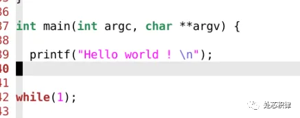
SOC验证C代码中如何打印字符串? 嵌入式微处理器2023年04月27日13:00四川学过C语言都知道,在程序中添加打印信息有助于我们追踪程序执行的情况。特别是debug的时候,打印一些log信息对快速定位到问题非常有帮助。怎么在SOC验证的C代码中打印字符串呢?用printf ?下面,我们来试一下:执行结果:没有出现 Hello world。这种结果是符合预期的。C code 通过GCC编译生成bin文件然后送到CPU中按指令进行执行。我们看下这段代码编译出来的指令是什么?这里 printf 编译出来是jump到一个puts的函数里面。puts函数又是什么呢?puts 又跳到 _puts_r ,依次下去,由printf 编译出了一系列的指令代码。由于CPU最终综合成版图,因此在CPU的RTL代码中不会存在读到某条指令打印一个字符串的功能。所以单纯的调用printf 并不会在log中打印字符串信息。如何实现打印?两个思路,第一个思路,在SOC的TB里面增加一个CPU bus的monitor,我们在monitor中实现一个功能,当看到特定地址,特定数据的时候,开始收集要打印的字符串,当看到特定地址,另外一个特定数据的时候,结束字符串的收集,并将收集到字符串打印。以下是我们在一个project中看到特殊数据 24’hdddd_11xx 开始收集字符串。以下是我们在一个project中看到特殊数据 24’hdddd_eeee 时打印字符串。这样,我们可以在c里面实现一个打印字符串的函数。通过上面这种手段,我们巧妙的将C语言的打印和 verilog的 $display 打印连接起来。我们来看看效果Hello World 打印出来了。我们再看看 puts编译后的代码是什么?这次 puts并没有跳转到 _puts_r ,而是向特定地址发送特定数据表示开始,然后传输字符串,并以特定数据结束。当我们的monitor检查到这些特殊的数据时就会打印出log信息。上面打印的方式可以解决在SOC验证环境中打印 字符串的问题,但是在芯片流片回来之后,在C中调用上述函数还能打印吗?显然是不可以的,因为这个时候外部的monitor都没有了,更别说不能综合的display函数等。下面介绍一种更加普遍的使用方法。我们在嵌入式硬件开发的过程中经常用到串口调试工具。通过简单的几根线与电脑连接,然后用串口调试助手就能将SOC和电脑调试界面连接起来。因此,在我们SOC验证环境中集成UART的slave device,在UART device收到数据后,打印出字符串信息是一个很好的选择。为此,我们通过向uart device写字符串的形式,然后在UART device中实现打印功能。我们来测试下用上面这种方式打印的效果,prints 是我们向uart 发送字符串的函数。下面是执行效果:同样实现了打印,而且这种打印方式在后续芯片流片回来之后可以通过串口调试 查看打印的信息。看到这里,大家明白怎么在SOC中实现字符串打印了吧~
-
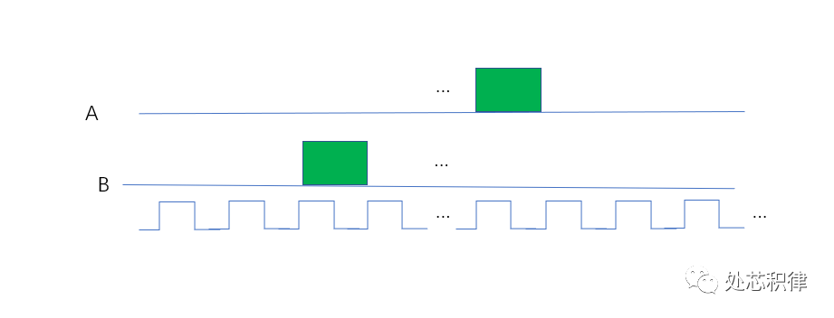
芯片验证随机(random)的六宗罪 IP与SoC设计2023年04月19日12:04江苏以前看到不少验证技术书籍都在说验证环境中随机怎么怎么好,然后为了随机,UVM,SV 提供了什么什么支持。但是最近的一些工作小编发现在验证中采用随机存在很多缺点。下面小编带大家看看使用随机带来的六宗罪。第一宗罪:难以debug出现fail的test,当debug完,对设计和验证环境做了改动,可能无法复现fail的场景。如何确保发现的testbench的问题,或者RTL的问题有真的修掉?一般的做法是用同样的seed,然后跑一遍之前的fail的test。但是有很多时候,由于环境的文件,约束等改变,再用同样的seed 跑fail 的test 和之前的行为不一致,从而错误的认为问题已经修掉。第二宗罪:难以覆盖到特定场景有些场景通过随机撞到的概率非常低。如下图所示,C = A &&B,在下图场景中想通过 随机到 (A==1)&&(B==1)的 场景,非常难。第三宗罪:验证时间不确定回归结果不可靠。一次通过率100%,不代表次次回归100%。一次回归可能100%,第二次回归又变成90%。连续10次回归100%,第十一次回归又出现fail的test。第四宗罪:重复测试用例很多浪费太多license 和服务器资源。因为单次regression不能保证没有问题,所以要周周跑,月月跑,一直跑到tapout,这浪费了很多license和服务器资源。特别是有些test 打到的场景重复,做一些无效验证,给公司资源造成极大浪费。第五宗罪:覆盖率收集耗费资源coverage 收敛比较耗时间和资源。由于随机约束造成不同场景出现的概率不一样,通过随机测试将代码覆盖率和功能覆盖率补全需要经过大量的回归测试。coverage的收敛速度没有直接测试来得快。下面是一个案例,在跑完一版regression后,功能覆盖率是80.49%。我们想将该功能覆盖率补全,采用直接测试用例,我们调用了5次测试,可以将覆盖率打到95.90% ,剩下的部分可以waive掉。当我们采用随机测试,调用了5次随机测试,覆盖率为90.62%。当我们采用随机测试,调用了10次随机测试,覆盖率为93.97%。当我们采用随机测试,调用了20次随机测试,覆盖率为95.90%,达到了和直接测试同样的效果。第六宗罪:场景打不全随机验证打不全所有场景如上图所示,随机的行为很难将所有的测试路径都打到。随机有没有好处呢?当然有,比如探索更多的场景:随机验证可以探索更多的测试场景,覆盖更多的状态空间。这可以帮助发现设计中的潜在问题和漏洞,从而提高验证的质量。发现意外错误:随机测试可以揭示一些设计者未曾考虑的异常情况,以及在正常测试中可能被忽略的边缘情况。这有助于找到并修复一些潜在的设计错误。减少人为偏见:手动创建测试用例可能受到验证工程师的认知偏见和经验限制的影响。随机验证方法可以降低这种偏见对验证结果的影响,从而提高验证的可靠性。减少人工编写测试用例的时间和精力:随机验证方法可以自动生成大量测试用例,从而减少人工编写测试用例的时间和精力。这有助于缩短验证周期,提高验证效率。更好地应对复杂性:随着芯片设计变得越来越复杂,人工创建足够多的测试用例以覆盖所有可能的场景变得越来越困难。随机验证方法可以在面对复杂设计时自动生成更多的测试用例,从而更好地应对这种复杂性。使用随机验证存在很多问题,但它仍然是一种非常有效的验证方法。为了克服这些缺点,我们可以将随机验证与其他验证方法(如指导性验证、形式验证等)相结合,以实现更全面、有效的芯片验证。来自微信